Basic UML symbols
Yesterday’s post about UML diagrams introduced us to why UML diagrams are useful, but knowing how something is useful doesn’t really help us use it to well. I decided today’s post will be a breakdown of some of the most commonly used symbols in UML.
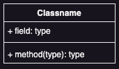
1. Class
The class symbol is represented as a rectangle divided into three sections: the top section contains the class name, the middle section holds attributes (variables), and the bottom section lists methods (functions). It’s commonly used in Class Diagrams to define the structure of a system.
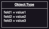
2. Object
Similar to the class symbol but with underlined text, the object symbol is used in object diagrams to represent an instance of a class, showing real-world examples of how objects interact.
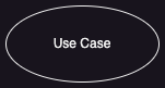
3. Use Case
A use case symbol is depicted as an oval or ellipse and is used in Use Case Diagrams to describe a functionality or a scenario where users interact with the system. Actors (stick figures) are connected to these ovals to represent who performs each action.
4. Actor
In Use Case Diagrams, an actor symbol is typically a stick figure that represents users or external systems interacting with the system. Actors are linked to use cases to depict who initiates an action.

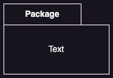
5. Package
The package symbol resembles a folder and is used in Package Diagrams to group related classes, components, or elements into namespaces. It helps organize complex diagrams by showing how components are logically grouped.
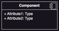
6. Component
A component symbol is drawn as a rectangle with two small rectangles on the side and is used in Component Diagrams to represent a physical, replaceable part of a system, such as a service or database.
7. Activity
The activity symbol, represented by a rounded rectangle, is used in Activity Diagrams to represent an action or task that needs to be performed. These diagrams show the flow of control between activities.

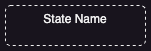
8. State
A state symbol is a rounded rectangle used in State Diagrams to represent different states an object can be in. Transitions between these states are shown using arrows.
These symbols form the backbone of UML, allowing system architects and developers to design, communicate, and understand systems more effectively. Each symbol serves a distinct purpose, and mastering them helps in creating clear and functional diagrams. Whether you’re working on high-level designs or detailed architecture, knowing these common UML symbols is essential!